Induction Loop Testing Equipment

Microloop III Instructions & Technical Specifications
Oval Window Audios Microloop III is a compact, high quality induction loop assistive listening system suitable for use at home as well as in classrooms, small meeting rooms and automobiles (with optional car kit). Its small size and light weight also make it the ideal portable small area loop system.
The Microloop III is compatible with all telecoil equipped hearing aids, cochlear implants and induction loop receivers.
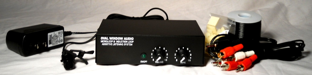
Your Microloop III system contains the following components:
- Loop amplifier
- 15 volt 1 Amp DC power supply
- 100 foot spool of 20 gauge loop wire
- Stereo patch cord for connecting to line output of TV and other equipment
- 10 self-adhesive loop wire clip
- Plug-in clip-on microphones w/10 cord.
- Plug-in table top microphones w/6' cord.
- Conference table microphones.
- Carrying case & shoulder bag.
- Loop pad.
- Car kit (cigarette lighter power cord, loop wire, clips).
- Microphone extension cord(s).
- Induction loop receiver(s)
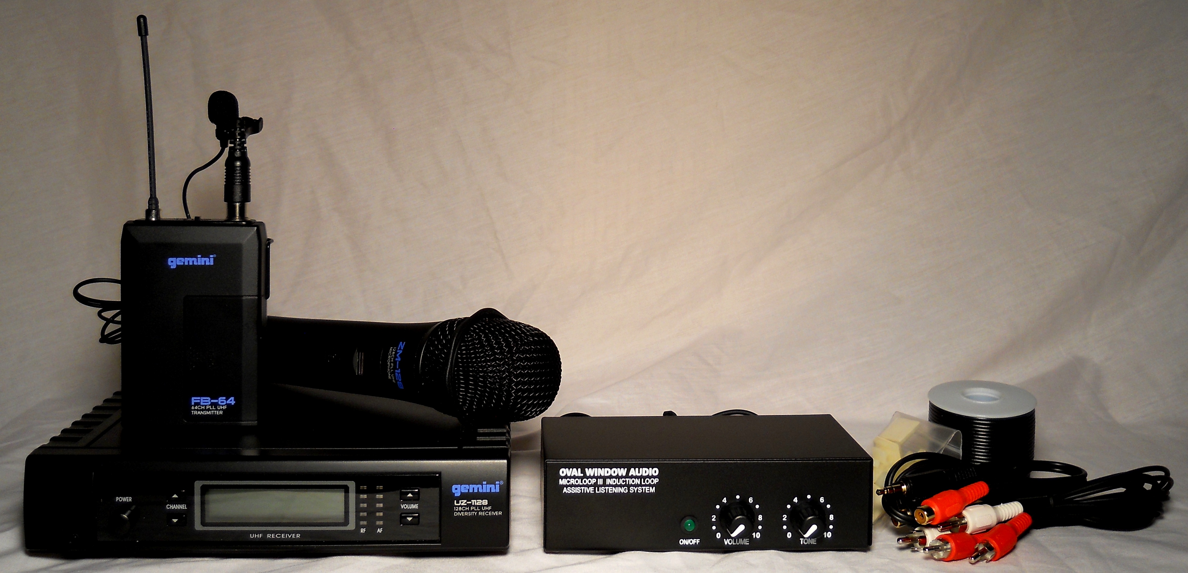
- UHF clip-on wireless microphone transmitter
- UHF hand held wireless microphone transmitter
- Wireless microphone receiver
- AC adapter (labeled "Gemini")
- Patch cord for connecting wireless microphone receiver output to Microloop MIC input
- UHF clip-on wireless microphone transmitter
Controls and Indicators
Front:
ON/OFF LIGHT: continuous green light when power is on; flashing indicates
overload
VOLUME: turns unit on and adjusts output of loop wire
TONE: increases high frequency (treble) sounds
Rear:
MIC 1 & MIC 2: accept corded Microloop clip-on and wireless microphone
systems
LINE INPUTS: connect to the LINE OUT of external equipment (e.g. radio, TV)
LOOP CONNECTIONS: accept each end of the supplied loop wire or loop pad
12-15V DC 1A: accepts the power supply provided with the
system
Telephone outputs may be connected to the Microloop III MIC input by
using adapter and/or patch cord available from the telephone manufacturer
or electronics store.
Microloop III installation precautions:
2. In order to maintain proper signal strength and signal uniformity, the height of the loop should not exceed 10 feet off the floor, and the loop perimeter should not exceed the 100 feet of wire supplied with the system.
3. The loop wire must completely encircle the listening area.
4. The loop wire must not be cut. If there is extra wire remaining, it may be left on the spool and tucked away. If half or more of the wire is not needed, run the wire a second or third time around the listening area. This will optimize the electrical load on the system while boosting the signal.
5. If the full 100 feet of loop wire is needed to encircle the area, lead-in wire may be added to connect back to the loop amplifier. 18 or 20 gauge lamp cord or loudspeaker wire is recommended.
6. Due to "dead spots" that occur directly above and below the loop wire, the installed loop wire should not be situated directly above or directly below seating within the listening area.7. The loop wire must not be run in continuous contact with metal, either directly above or below the loop wire. Loop wires may cross metal furnishings or ceiling and wall framework/studs. At least 70% of the total loop wire must be free of metal obstructions.
8. At least 70% of the loop wire should be installed in the horizontal plane.9. A loop system will transmit signals that spill outside the looped listening area. At least twice the length of the longest side of the loop should be allowed between looped areas on the same floor. Loop systems on different floor levels should be separated by at least one-half the length of the longest side of the loop wire.
10. In some listening environments, additional power is needed to overcome background electrical noise, or to offset losses due to metal furniture and/or building materials. To boost power, additional 20 gauge loop wire may be connected in series (end to end) with the existing wire in order to create a multi-turn loop. Total number of turns should generally not exceed three.11. Avoid running loop wire in close proximity and parallel to telephone lines, microphone cords and video feeds. Maintain a distance of at least 12".
12. The Microloop III may be installed in vehicles. Please contact Oval Window Audio for more information regarding the Microloop III Car Kit.13. The microphone supplied with the Microloop III is very sensitive and may be held or clipped onto the speaker. For small meetings, the microphones may be placed flat on a tabletop, centered 3 to 5 feet from those speaking.
14. Only electret powered microphones should be used. Both electret and wireless microphones compatible with the Microloop III are available from Oval Window Audio.Installation:
1. Plug the black AC adapter into a power strip or wall outlet and other end into the 12-15V DC jack at the rear of the Microloop III amplifier.2. Insert microphone plug(s) into either of the two microphone jacks labeled MIC 1 and MIC 2 at the rear of the amplifier, and then clip onto clothing of speaker(s), not more than 6 inches from the mouth.
3. For conferencing, one or two microphones may be placed flat on the meeting table, positioned 3 to 5 feet from the speakers.
4. For radio or TV listening, connect the supplied patch cord from the LINE OUTPUT of the external equipment (e.g. TV, satellite receiver, cable box, stereo system or personal audio device) to the LINE INPUTS of the Microloop III amplifier. If analog audio outputs are not available, please contact Oval Window Audio to learn about the Digital to Analog Converter. Alternatively, if the equipment does not have audio line outputs, place the Microloop microphone close to the loudspeaker using the supplied Velcro pads.
5. Connect one bare wire end of the loop wire spool to one of the LOOP CONNECTIONS at the rear of the amplifier by pushing in the terminal and inserting the bare wire end. Do not release the push terminal onto the wire insulation. It doesn't matter which terminal (red/black) is used.
6. Spool out the wire required to encircle the listening area and return with the remaining wire to the amplifier. Unused loop wire should be left on the spool. If a very small area is being looped (e.g. 50 feet or less), run additional turn(s) of wire around the listening area in the same direction as the first wire until all or most of the wire is used up.
7. Connect remaining bare end of wire to second terminal of LOOP CONNECTIONS at the rear of the Microloop III amplifier.
8. At the back of the Microloop III, maintain separation between the loop wires and the line input and/or microphone cords.
9. Rotate VOLUME control. ON/OFF green LED will illuminate.
Checking the System:
1. While situated inside the loop, listen with a hearing aid switched to "T/telephone or an Induction Loop Receiver and adjust the Microloop IIIs VOLUME and TONE controls for the strongest and clearest signal from the connected microphones and/or external equipment. If the sound is distorted, turn the VOLUME down.2. If ON/OFF green LED flashes indicating overload, decrease VOLUME control until the flashing stops. If flashing continues, check that the loop wire is not shorted
Wireless microphone systems (Microloop III FM, Microloop III Dual FM):
1. Connect the AC adapter (labeled "GEMINI") to the wireless microphone receiver and wall outlet.
2. Using the supplied patch cord, connect the output of the wireless microphone receiver to one of the microphone inputs of the Microloop III amplifier marked MIC 1 and MIC 2.3. Insert the supplied batteries into the wireless microphone transmitter.
4. Set the VOLUME control to mid-position. When using the clip-on microphone in combination with wireless microphone(s), first set a comfortable level with the clip-on microphone alone. While listening to the loop system, adjust the wireless microphone receiver's LEVEL/VOLUME/OUTPUT control(s) for an equal balance of sound from all of the microphones.5. The microphone transmitter's rechargeable option may be employed by ordering the required charge cord & NiMH batteries. For more detailed information on the wireless microphone system please refer to the separate enclosure.
Warranty:
All Oval Window Audio products are sold on a 30-day satisfaction guaranteed basis and with a 3-year warranty covering parts and labor. Exceptions to this warranty include microphones, rechargeable batteries and ear/headphones which are guaranteed for 90 days. Warranty will be voided for equipment that has been abused, altered or operated in a manner contrary to directions contained in the user manual. A return authorization must be obtained for all equipment returns and servicing (please see information below).
Customer & Technical Support:
OVAL WINDOW AUDIO
33 Wildflower Court
Nederland, CO 80466 USA
Telephone: (303) 447-3607
info@ovalwindowaudio.com
MICROLOOP III Technical Specifications:
Inputs & Outputs:
Two microphone inputs: (3.5mm1/8" miniphone jacks), 1-100 millivolt
sensitivity, 600 Ohm, 6 volt phantom powered for Oval Window Audio
electric microphone(s). Note: the sensitive omni-directional microphones
available for the Microloop can function as conference table microphones
by setting them flat on table surface, positioned 3-5 feet from speakers,
or TM-1 microphones may be used (click here for information).
Line level input (RCA phono jacks): 150 millivolt to 10 volts RMS, 600-10K Ohms (Automatic input gain control maintains consistent signal levels).
Loop wire push terminal connector output: 2.6 amps @ 1kHz into 1 Ohm
Wireless microphone/s (Microloop III FM/Microloop III Dual FM):
Choice of clip-on or handheld UHF band wireless microphone systems with
150 foot range, includes patch cord for interfacing with Microloop
amplifier. Rechargeable options are available.
Controls:
Volume control sets maximum output of the loop amplifier.
Tone control acts as treble boost, maximum +10 dB @ 10 kHz.
Field strength:
100 milliamperes/meter average w/ peaks of 400 milliamperes/meter measured
39" above the center of the supplied 100 foot loop as per IEC 118-4: 2006
specifications.
Microloop loop wire:
100 foot 20 gauge (1/16" O.D.) stranded single conductor on small spool
(choice of black or white). A boosting of the signal strength can be
achieved by increasing the number of turns of the loop wire. The 100 foot
perimeter limit should not be exceeded, and the maximum number of turns
should not exceed three. In order to maintain optimum electrical match,
the loop wire must not be cut.
Power supply:
Switching supply: input: 100-240V AC, 47-63 Hz; output: 15 V DC 1000
milliamperes wall adapter w/ 2.1mm jack. The Microloop may also be used in
vehicles with the optional cigarette lighter cord.
Frequency response:
In accordance with IEC 118-4 frequency response 100 Hz-5 kHz +/-3dB
Dimensions & weight:
Amplifier: 5.75" W x 3 "D x 1.6" H (suitable for 1/3 rack mount
installations)
Carrying case: 9" W x 6" D x 6" H (Microloop III), 15" W x 7" D x 7" H (Microloop
III FM/Dual FM)
Microloop III: 3 pounds; Microloop III FM: 4 pounds; Microloop III Dual
FM: 5 pounds
Microloop III accessories include:
Car kit (cigarette lighter power cord, loop wire, self-adhesive loop wire clips),
additional microphones (omnidirectional, directional, head worn,
conference and wireless), digital to analog converter, 10 & 25-foot microphone extension cords, Y cords
for connecting additional microphones, and rechargeable battery options
for wireless microphones
![]()
![]()
E-mail Oval Window Audio Today
Home // Hearing Loops // Induction Loop Assistive Listening Systems // Induction Loop Receivers // Induction Loop Testing Equipment // Vibrotactile/Multisensory Sound Lab // Loop Systems & Accessories Pricing & Ordering // Contact Us
This site created with the help of The Write Direction.