Induction Loop Receivers
Induction Loop Testing Equipment

Bridging Satellite III Induction Loop Amplifiers
By “bridging”
two Satellite
III loop amplifiers, it is possible to substantially increase maximum
loop wire
coverage, from 325 feet (6,600 SF) to 500
feet (15,600 SF).
- Maximum loop wire perimeter per bridged pair of amplifiers should not exceed 500 feet.
- Only the 14G wire
supplied with the system should be used for the actual loop…one 500
foot
spool
is provided.
- Two conductor 14G
lead in wire (not supplied) may be used to connect the amplifiers to
the loop
wire if the distance is not greater than 50 feet.
- 12G wire should
be used for lead in runs of 50 to 100 feet.
- 10G lead in wire
should be used for runs exceeding 100 feet.
- The total
run of wire,
including lead in to
the amplifiers, should be at least 500 feet to maintain proper loading
of the
amplifiers.
- Ideal DC
resistance of the lead in + loop wire is 1.5 to 1.7 Ohms (the Ohm meter
test
lead resistance should be subtracted from the measurement).
- For
proper air
circulation when rack mounting, locate the two amplifiers so that there
is at
least 1 inch of space between the amplifiers, and 1 inch above and
below them.
- For
detailed Satellite
III installation and set up directions, please refer to the Satellite
III
instruction manual.
Please
familiarize
yourself with the Satellite III rear panel layout as shown:
- AC power cord
- Switched outlet, 2A maximum
- Paralleled unbalanced phono jack inputs
- Equalization adjustment (preset to maximum, fully counterclockwise)
- Balanced input terminal strip
- Phase invert switch for bridging two Satellite IIIs, must be switched to opposite settings (e.g. first amplifier switch pressed in on top, second amplifier switch pressed in on bottom)
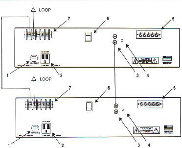
Please refer to the
above illustration for the following instructions (you may click on the
image for an enlarged version):
- Connect a length of 14G wire between the “C” terminals (#7) of the amplifiers.
- Connect one end of the loop lead in wire to one of the amplifier’s 1 Ohm output terminals (#7).
- Connect the other end of the loop lead in wire to the other amplifier’s 1 Ohm output terminal (#7).
- Set the rocker switch (#6) on both amplifiers to opposite settings.
- Plug one end of the supplied patch cord into either one of the inputs (#3) of the first amplifier.
- Plug the other end of the patch cord into either of the inputs (#3) of the second amplifier.
- Insert the audio line level signal source into either amplifier’s open input jacks (#3). If the balanced inputs are needed, the individual terminals will need to be paralleled and connected to the balanced line level signal source.
- Check that the equalization trimmer (#4) is set fully counterclockwise on both amplifiers.
- Plug the amplifiers’ AC cords into outlets rated at least 15A. Total load of both Satellite IIIs will not exceed 6A.
- Check that the Volume and Limiter controls of both amplifiers are set to 0.
- Switch on the power to both amplifiers.
- Send an audio feed signal to the amplifiers that represents a typical maximum signal level/normal operating level (e.g. “0” on the meter of the sound system’s mixer or comfortable listening volume).
- Simultaneously increase Volume controls on both loop amplifiers until the amplifiers’ Peak LEDs illuminate brightly and continuously. At this point, both Volume controls should be approximately set to the same setting.
- Simultaneously increase the Limiter controls on both
loop amplifiers until the
amplifiers’ Peak LED softens and lights up brightly on signal peaks.
- Using the Induction Loop Receiver supplied with the system, hold it in an upright, vertical position and walk around the looped area while listening to the signal. The loop signal should be clear and free of distortion.
- At the approximate center of the looped area, the Induction Loop Receiver’s LED should light up at the signal peaks, indicating proper field strength. For information on more exacting measurements and installation certification, please contact us concerning the FSM Induction Loop Test Set.
IF THERE IS NO OUTPUT
FROM THE
- Check
that the phase invert
switches (#6) are
switched to opposite settings.
- Check
that the phase invert
switches on both
amplifiers are fully pressed in to
their required settings.
![]()
 E-mail
Oval Window Audio Today
E-mail
Oval Window Audio Today
Home Page // Hearing Loops // Induction Loop Assistive Listening Systems // Induction Loop Receivers // Induction Loop Testing Equipment // Vibrotactile/Multisensory Sound Lab // Loop Systems Accessories Pricing & Ordering // Contact Us
This site created with the help of The Write Direction